Three Basic Knowledge of Pogo Pin
This article will look at:
- The Basic Design concept of Pogo Pin
- The Basic Plunger design of Pogo Pin
- The Basic Working height of Pogo Pin
The Basic design concept of Pogo Pin(spring-loaded connector):
The basic Pogo Pin structure consists of 3 main parts: a plunger, barrel, and spring.
The high current Pogo Pin would use an extra ball or shell inside the barrel. The electrical characteristics will find the path with the least resistance to conduct the current)
The current will be conducted from the needle shaft to the wall of the outer tube and then to the PCB. At this time, the resistance value is the smallest.

The Basic plunger design of Pogo Pin(Spring-loaded connector):
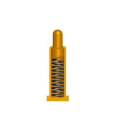
Bias Tail
The Bias Tail design is the most common and cheapest to produce with a good balance between performance, price, and size. This design can guarantee stable bottom impedance.
Advantage: Low and stable resistance
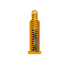
Back Drill
The back drill is usually used in an environment with small connectors, such as wireless earbuds, smartphones, or small IoT devices. the small size can meet the elasticity requirements of customers because the spring length of this design can exceed the length of the needle tube. In some cases where space is limited.
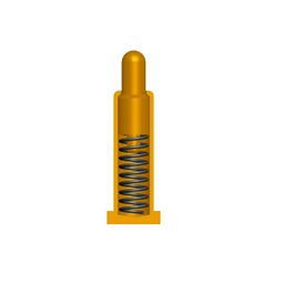
Cone Design
This kind of design is the best choice for the connector with high concentricity requirements because spring can be best set on the tapered tail pin of pin axle directly. tapered tail on the bottom of pin axle is placed in the inside of spring,to decrease the shake of pin axle. Advantage: Easy turning, Little skewness, Low cost.
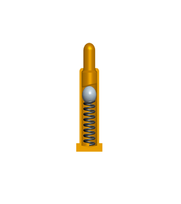
Ball Design
The ball design is the best option for challenging environments such as heavy-duty machines, charging, and medical applications, the contact is more stability and high current is important.
Advantage: Stable resistance, Can go through High current
The Basic working height of Pogo Pin(spring-loaded connector):
Generally, the amount of compression during operation is 2/3 of total travel, if the amount of compression is sufficient, the positive force is too low so that the impedance is not stable.
Using a pogo pin at working height will increase the durability and performance of the connector significantly.
The battery contact plate or golden finger that connects the pogo pin shall be free from dirt, oxidation, etc.
Please restrict the use within the range of specifications stated in the drawing.


Leave a Reply